 7 w5 L9 c+ `/ X 7 w5 L9 c+ `/ X
# M, w. O# M* K9 ], M8 p
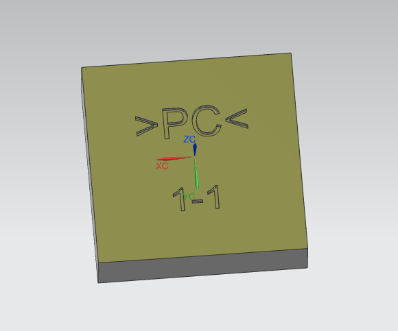
使用【分析】-【测量距离】,先测量一下字体的宽度,这样才能去选择合适的刀具,如下图所示: 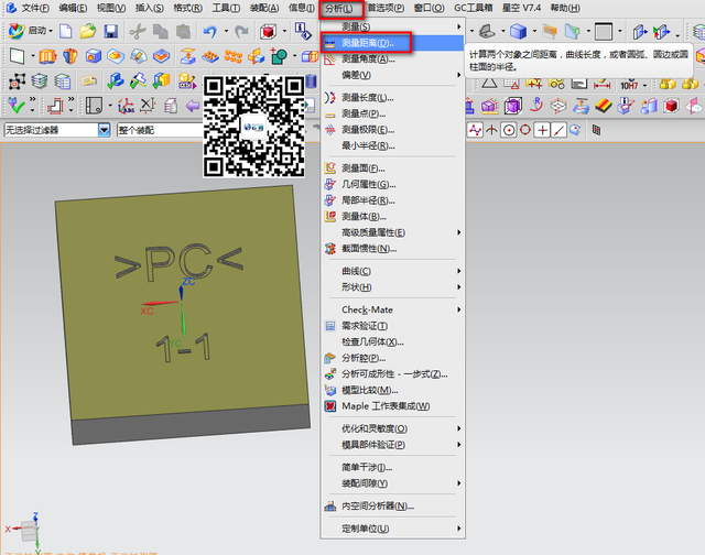 ! _" R1 B- p+ l$ Z2 ~8 |+ ^ ! _" R1 B- p+ l$ Z2 ~8 |+ ^
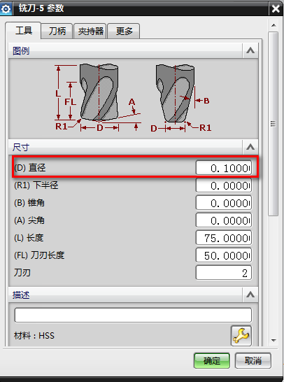
+ d* A( g# K- k! q% \7 g7 s测量距离为0.13MM左右,只要是大于此宽度的刀具都无法进去,我们只有使用D0.1的刀具,如下图所示: 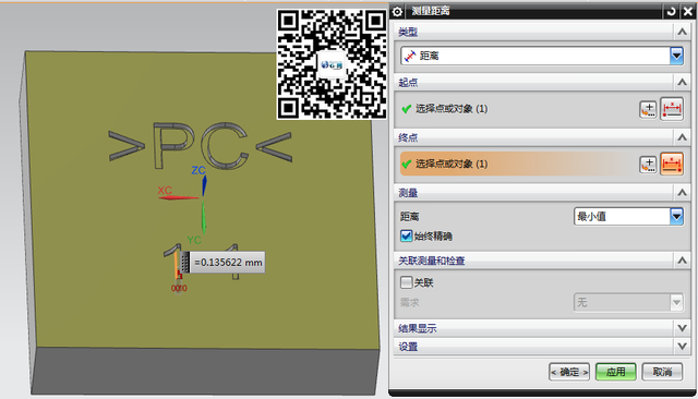
0 e( N5 _1 Y% W3 H+ r/ n6 ^! p) @( K
创建刀具,D0.1,输入直径为0.1MM,如下图所示: 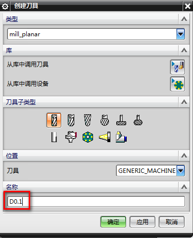 9 ?; H! j1 u! ^6 C) G V7 W 9 ?; H! j1 u! ^6 C) G V7 W
2 v) Q) B5 h1 X: ^
 : O a' D4 u/ ~( K9 @ : O a' D4 u/ ~( K9 @
" Y/ m8 o( k7 n【创建工序】-【mill-contour】,选择【实体轮廓3D】工序,如下图所示: 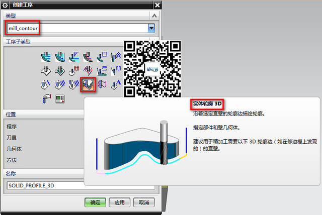
$ c0 c* O f8 ^
% F* L* }% U2 X; v% Y4 G在工序界面,【指定部件】选择要加工的实体,如下图所示: 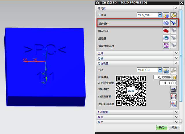 / C6 V* n7 ?9 I2 q0 r2 o# ^ / C6 V* n7 ?9 I2 q0 r2 o# ^
8 E- E! D) Q) k0 X
【指定壁】选择要加工字体的侧面,如下图所示: 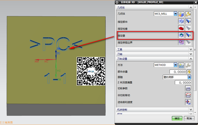
8 L% n9 w0 D0 t2 \$ n+ w( y
! q! M7 w: b3 H& W/ Y1 ?, \测量字体的深度为0.2MM,如下图所示: 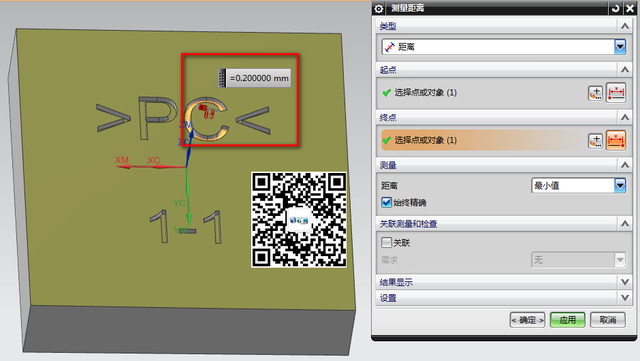
: a# H) ^$ Z5 @+ _. `
) E, K; N7 F. M& B$ R5 W【切削参数】-【多刀路】-【多重深度】,【深度余量偏置】0.2MM,【增量】0.02MM,如下图所示: 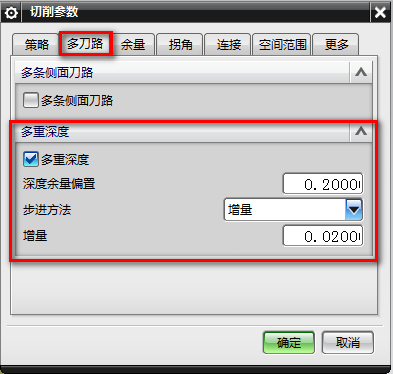 4 b) s5 X/ x( o 4 b) s5 X/ x( o
& F( B$ }3 l0 n/ P2 x" S【非切削移动】,【进刀】-【进刀类型】-【插削】-【高度】0.5MM,如下图所示: 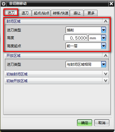
( B9 W- r* j# K6 l7 M1 I5 T! a* t# c0 l3 ]4 t% U* u
【非切削移动】-【转移/快速】,【区域内】-【转移类型】-【安全距离】0.5MM,如下图所示: 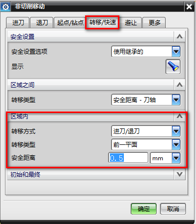 2 F0 e8 j# R6 j8 p 2 F0 e8 j# R6 j8 p
* B1 t" s+ P& U参数设置完成后,生成刀路,得到凹槽字码的程序,如下图所示: 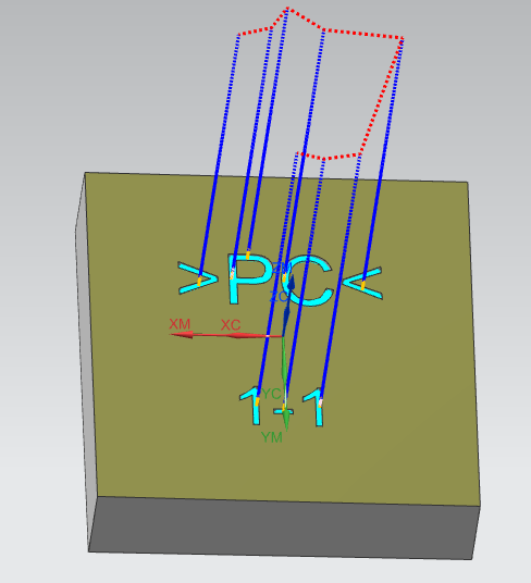
v& Q, P$ P& B- j# Z: J8 V6 X/ F
& m1 m& J: t7 u& @ | 
 |关于我们|sitemap|小黑屋|Archiver|手机版|UG网-UG技术论坛-青华数控模具培训学校
( 粤ICP备15108561号 )
|关于我们|sitemap|小黑屋|Archiver|手机版|UG网-UG技术论坛-青华数控模具培训学校
( 粤ICP备15108561号 )


 狗仔卡
狗仔卡 发表于 2021-7-18 15:34
 提升卡
提升卡 沉默卡
沉默卡 喧嚣卡
喧嚣卡 变色卡
变色卡 抢沙发
抢沙发 千斤顶
千斤顶 显身卡
显身卡